
TM 5-2420-231-23-2
0142
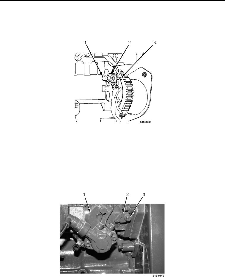
REMOVAL CONTINUED
6. Install timing pin (Figure 5, Item 1) in timing pin access cover (Figure 5, Item 2).
7. With assistance, using engine turning tool, rotate engine until timing pin seats in timing gear hole
(Figure 5, Item 3).
Figure 5. Timing Gear Hole.
0142
8. Loosen, but do not remove, locking bolt (Figure 6, Item 3) on high-pressure fuel pump (Figure 6, Item 1).
9. Remove spacer (Figure 6, Item 2) from high-pressure fuel pump (Figure 6, Item 1).
CAUTION
Do not overtighten locking bolt. Failure to follow this caution may result in damage to the
machine.
10. Tighten locking bolt (Figure 6, Item 3) on high-pressure fuel pump (Figure 6, Item 1).
Figure 6. High-Pressure Fuel Pump Locking Bolt.
0142