
TM 5-2420-231-23-2
0142
REMOVAL CONTINUED
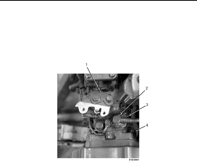
13. Push fuel line lock (Figure 8, Item 3) forward to unlock fuel line (Figure 8, Item 2).
14. Disconnect fuel line (Figure 8, Item 2) from high-pressure fuel pump (Figure 8, Item 1).
15. Remove three nuts (Figure 8, Item 4) from high-pressure fuel pump (Figure 8, Item 1).
CAUTION
Nuts hold high-pressure fuel pump in position while disengaging pump gear. Failure to
properly install nuts may cause damage to the machine.
16. Loosely install three nuts (Figure 8, Item 4) on high-pressure fuel pump (Figure 8, Item 1) three complete turns.
Figure 8. High-Pressure Fuel Pump.
0142