• Home
  • Download PDF
  • Order CD-ROM
  • Order in Print
Figure 3. High-Pressure Fuel Tubes Installation.
Figure 6. High-Pressure Fuel Tubes.

Tractor, Wheeled, Industrial Backhoe Loader Nsn 2420-01-532-3399
Page Navigation
  374    375    376    377    378  379  380    381    382    383    384  
img
.
TM 5-2420-231-23-2
0145
INSTALLATION CONTINUED
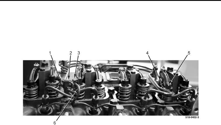
7. Install clamp assembly (Figure 5, Item 4) and bolt (Figure 5, Item 5) on engine.
8. Install clamp assembly (Figure 5, Item 2) and bolt (Figure 5, Item 1) on engine.
9. Position fuel return tube (Figure 5, Item 6) in clamp (Figure 5, Item 3).
10. Lock clamp (Figure 5, Item 3).
Figure 5. High-Pressure Fuel Tubes Installation.
0145
0145-5


Privacy Statement
Press Release
Contact

© Copyright Integrated Publishing, Inc.. All Rights Reserved.