
TM 5-2420-231-23-2
0145
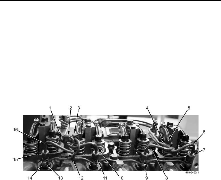
REMOVAL CONTINUED
9. Release clamp (Figure 2, Item 3) and position fuel return tube (Figure 2, Item 12) aside.
10. Remove bolt (Figure 2, Item 1) and clamp assembly (Figure 2, Item 2) from engine.
11. Remove bolt (Figure 2, Item 5) and clamp assembly (Figure 2, Item 4) from engine.
12. Remove four bolts (Figure 2, Item 14), seal washers (Figure 2, Item 13), and fuel return tube (Figure 2,
Item 12) from engine. Discard seal washers.
NOTE
Note position and location of high-pressure fuel tubes to aid in installation.
13. Loosen nut (Figure 2, Item 11) and remove high-pressure fuel tube (Figure 2, Item 10) from engine.
14. Loosen nut (Figure 2, Item 15) and remove high-pressure fuel tube (Figure 2, Item 16) from engine.
15. Loosen nut (Figure 2, Item 9) and remove high-pressure fuel tube (Figure 2, Item 8) from engine.
16. Loosen nut (Figure 2, Item 7) and remove high-pressure fuel tube (Figure 2, Item 6) from engine.
Figure 2. High-Pressure Fuel Tubes Removal.
0145
END OF TASK
CLEANING AND INSPECTION
0145
Clean and inspect all parts IAW Mechanical General Maintenance Instructions (WP 0369).
END OF TASK