
TM 5-2420-231-23-2
0145
INSTALLATION CONTINUED
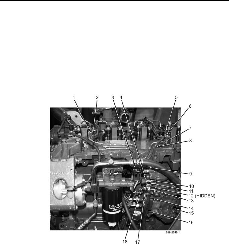
11. Install new crushwasher (Figure 6, Item 10), return tube (Figure 6, Item 4), new crushwasher (Figure 6,
Item 17), and nut (Figure 6, Item 18) on high-pressure fuel pump (Figure 6, Item 15).
12. Install clamp assembly (Figure 6, Item 3) and bolt (Figure 6, Item 9) on engine.
13. Install clamp assembly (Figure 6, Item 7) and bolt (Figure 6, Item 6) on engine.
14. Position fuel return tube (Figure 6, Item 8) in clamp (Figure 6, Item 5).
15. Lock clamp (Figure 6, Item 5).
16. Install clamp assembly (Figure 6, Item 2) and bolt (Figure 6, Item 1) on engine.
17. Tighten all high-pressure fuel tube nuts.
18. Install new O-ring (Figure 6, Item 12) and connect elbow (Figure 6, Item 13) to high-pressure fuel pump
(Figure 6, Item 15) and install lock (Figure 6, Item 11).
19. Install new tiedown strap (Figure 6, Item 14) on fuel hose (Figure 6, Item 16).
Figure 6. High-Pressure Fuel Tubes.
0145
END OF TASK