
TM 5-2420-231-23-2
0169
INSTALLATION CONTINUED
WARNING
Allow hydraulic system to cool before performing procedure. Hot hydraulic fluid can cause
severe burns. Wear eye, hand, and skin protection when working with heated parts.
Hydraulic oil is very slippery. Immediately wipe up any spills.
Failure to follow these warnings may result in injury or death to personnel.
NOTE
Install wires and lines as tagged and marked during removal.
Remove plugs and caps from hoses and fittings.
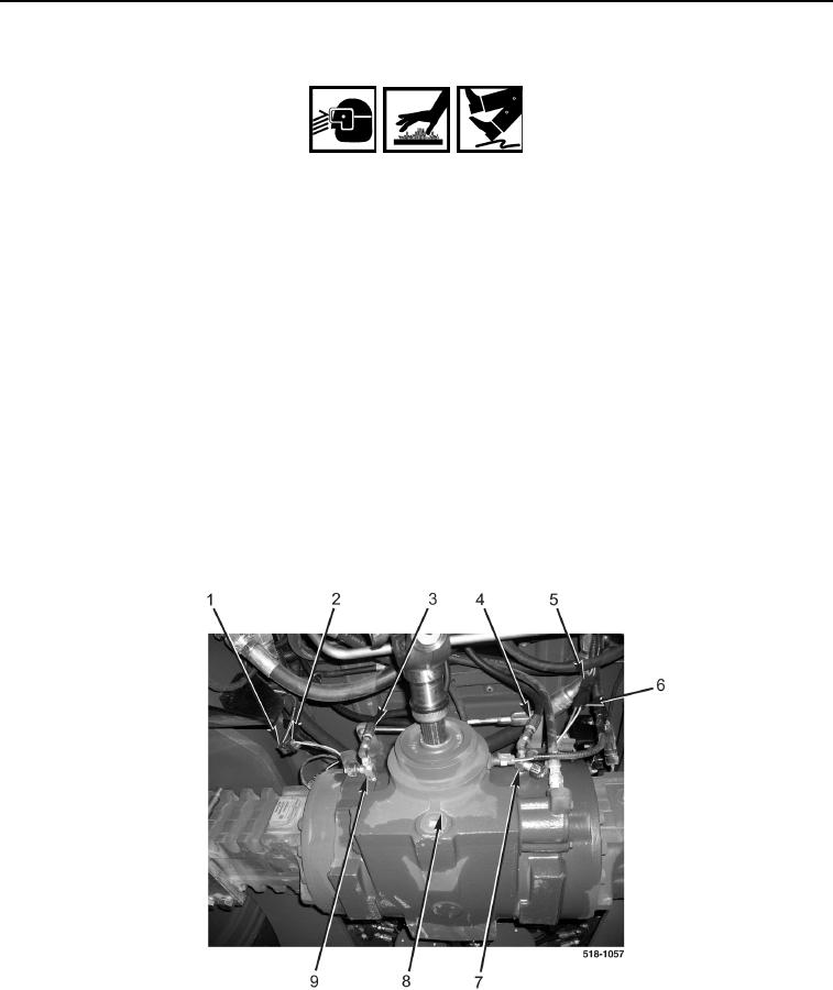
5. Install left fitting (Figure 4, Item 7) on axle (Figure 4, Item 8).
6. Connect left hydraulic brake hose (Figure 4, Item 4) to left fitting (Figure 4, Item 7).
7. Install right fitting (Figure 4, Item 9) on axle (Figure 4, Item 8).
8. Connect left hydraulic brake hose (Figure 4, Item 3) to right fitting (Figure 4, Item 9).
9. Connect left brake pressure sensor wiring connector (Figure 4, Item 6) to machine wiring connector
(Figure 4, Item 5).
10. Connect right brake pressure sensor wiring connector (Figure 4, Item 2) to machine wiring connector
(Figure 4, Item 1).
Figure 4. Brake Pressure Sensor Connections.
0169
END OF TASK