
TM 5-2420-231-23-2
0169
REMOVAL CONTINUED
NOTE
The procedure for brake pressure sensor removal and replacement is identical for left-
hand and right-hand brake pressure sensors. Left-hand brake pressure sensor is shown
in this procedure.
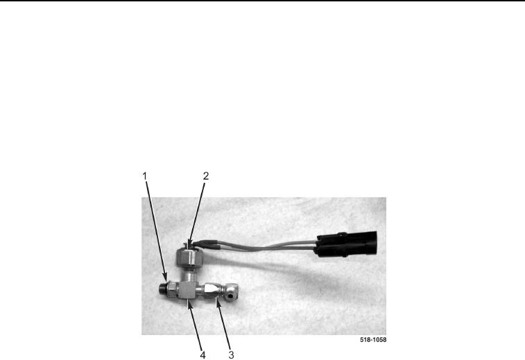
7. Remove O-ring (Figure 2, Item 1) from fitting (Figure 2, Item 3). Discard O-ring.
8. Remove brake pressure sensor (Figure 2, Item 2) from sensor block (Figure 2, Item 4).
9. Remove fitting (Figure 2, Item 3) from sensor block (Figure 2, Item 4).
Figure 2. Brake Pressure Sensor.
0169
END OF TASK
CLEANING AND INSPECTION
0169
1. Clean and inspect all parts IAW Mechanical General Maintenance Instructions (WP 0369).
2. Clean and inspect all parts IAW Electrical General Maintenance Instructions (WP 0370).
END OF TASK