
TM 5-2420-231-23-2
0172
REMOVAL CONTINUED
NOTE
Tag and mark wires to aid in installation.
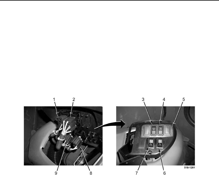
16. Disconnect connector (Figure 4, Item 1) from rear washer switch (Figure 4, Item 4).
17. Remove rear washer switch (Figure 4, Item 4) from throttle panel (Figure 4, Item 5).
18. Disconnect connector (Figure 4, Item 2) from rear wiper switch (Figure 4, Item 3).
19. Remove rear wiper switch (Figure 4, Item 3) from throttle panel (Figure 4, Item 5).
20. Disconnect connector (Figure 4, Item 9) from backhoe right hydraulic coupling switch (Figure 4, Item 6).
21. Remove backhoe right hydraulic coupling switch (Figure 4, Item 6) from throttle panel (Figure 4, Item 5).
22. Disconnect connector (Figure 4, Item 8) from backhoe left hydraulic coupling switch (Figure 4, Item 7).
23. Remove backhoe left hydraulic coupling switch (Figure 4, Item 7) from throttle panel (Figure 4, Item 5).
Figure 4. Throttle Panel Switches.
0172
END OF TASK
CLEANING AND INSPECTION
0172
1. Clean and inspect all parts IAW Mechanical General Maintenance Instructions (WP 0369).
2. Clean and inspect all parts IAW Electrical General Maintenance Instructions (WP 0370).
END OF TASK