
TM 5-2420-231-23-2
0172
INSTALLATION
0172
NOTE
Install wires as tagged and marked during removal.
1. Install backhoe left hydraulic coupling switch (Figure 4, Item 7) on throttle panel (Figure 4, Item 5).
2. Connect connector (Figure 4, Item 8) to backhoe left hydraulic coupling switch (Figure 4, Item 7).
3. Install backhoe right hydraulic coupling switch (Figure 4, Item 6) on throttle panel (Figure 4, Item 5).
4. Connect connector (Figure 4, Item 9) to backhoe right hydraulic coupling switch (Figure 4, Item 6).
5. Install rear wiper switch (Figure 4, Item 3) on throttle panel (Figure 4, Item 5).
6. Connect connector (Figure 4, Item 2) to rear wiper switch (Figure 4, Item 3).
7. Install rear washer switch (Figure 4, Item 4) on throttle panel (Figure 4, Item 5).
8. Connect connector (Figure 4, Item 1) to rear washer switch (Figure 4, Item 4).
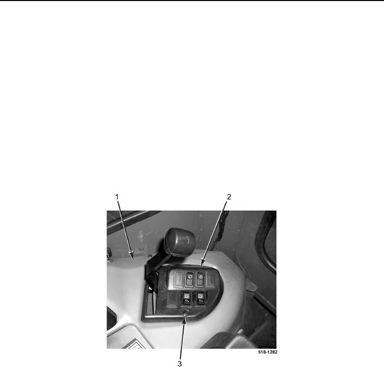
9. Install throttle panel (Figure 5, Item 2) on side console (Figure 5, Item 1).
10. Install screw (Figure 5, Item 3) on throttle panel (Figure 5, Item 2).
Figure 5. Throttle Panel.
0172