
TM 5-2420-231-23-2
0172
INSTALLATION CONTINUED
NOTE
Install wires as tagged and marked during removal.
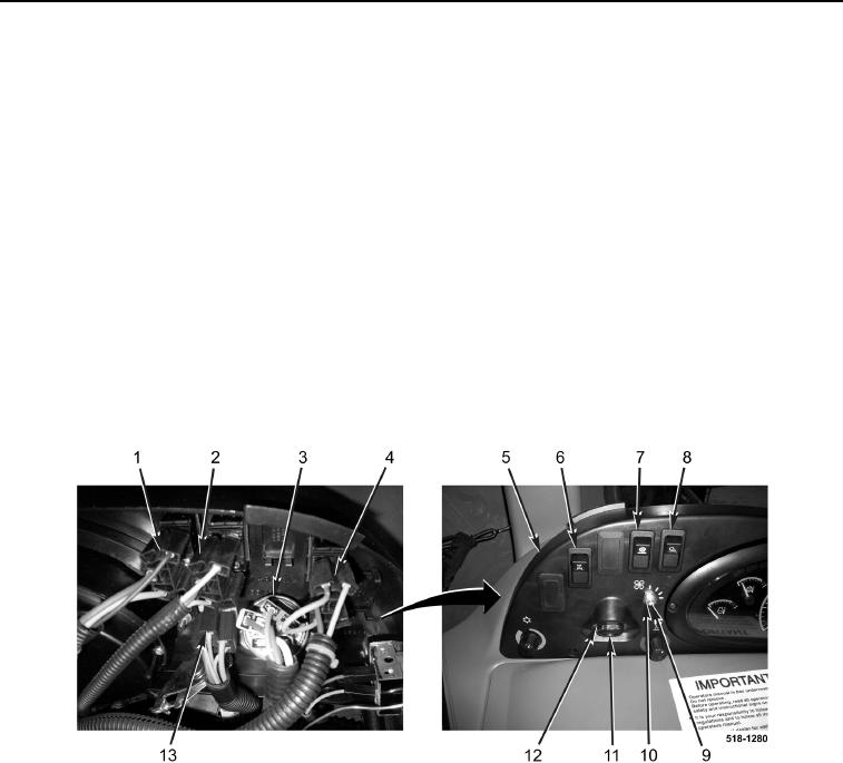
11. Install blower control switch (Figure 6, Item 9) and nut (Figure 6, Item 10) on instrument cluster
(Figure 6, Item 5).
12. Connect connector (Figure 6, Item 13) to blower control switch (Figure 6, Item 9).
13. Install ignition switch (Figure 6, Item 11) and nut (Figure 6, Item 12) on instrument cluster (Figure 6, Item 5).
14. Connect connector (Figure 6, Item 3) to ignition switch (Figure 6, Item 11).
15. Install light switch (Figure 6, Item 8) on instrument cluster (Figure 6, Item 5).
16. Connect connector (Figure 6, Item 1) to light switch (Figure 6, Item 8).
17. Install ride control switch (Figure 6, Item 7) on instrument cluster (Figure 6, Item 5).
18. Connect connector (Figure 6, Item 2) to ride control switch (Figure 6, Item 7).
19. Install four-wheel-drive switch (Figure 6, Item 6) on instrument cluster (Figure 6, Item 5).
20. Connect connector (Figure 6, Item 4) to four-wheel-drive switch (Figure 6, Item 6).
Figure 6. Cluster Switches.
0172