
TM 5-2420-231-23-2
0176
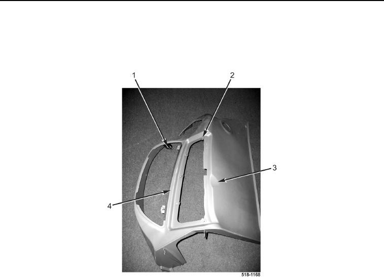
INSTRUMENT PANEL RIGHT-SIDE COVER (REAR) REMOVAL CONTINUED
18. Remove two accessory outlets (Figure 17, Item 1) from right-side cover (rear) (Figure 17, Item 3).
19. Remove strip (Figure 17, Item 4) from right-side cover (rear) (Figure 17, Item 3).
20. Remove eight clips (Figure 17, Item 2) from right-side cover (rear) (Figure 17, Item 3).
Figure 17. Right-Side Cover (Rear).
0176
END OF TASK
CLEANING AND INSPECTION
0176
Clean and inspect all parts IAW Mechanical General Maintenance Instructions (WP 0369).
END OF TASK
INSTRUMENT PANEL RIGHT-SIDE COVER (REAR) INSTALLATION
0176
1. Install eight clips (Figure 17, Item 2) on right-side cover (rear) (Figure 17, Item 3).
2. Install strip (Figure 17, Item 4) on right-side cover (rear) (Figure 17, Item 3).
3. Install two accessory outlets (Figure 17, Item 1) on right-side cover (rear) (Figure 17, Item 3).