
TM 5-2420-231-23-2
0176
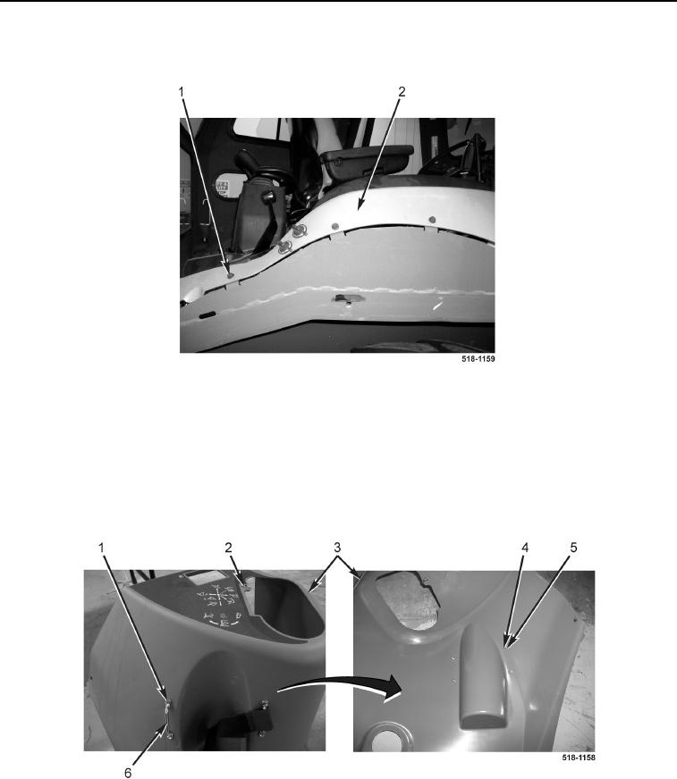
INSTRUMENT PANEL RIGHT-SIDE COVER (REAR) INSTALLATION CONTINUED
20. Install three bolts (Figure 26, Item 1) on right-side cover (rear) (Figure 26, Item 2).
Figure 26. Top Rear Console Bolts.
0176
END OF TASK
INSTRUMENT PANEL RIGHT-SIDE COVER (FRONT) INSTALLATION
0176
1. Install two fire extinguisher handles (Figure 27, Item 6), four screws (Figure 27, Item 1), four washers
(Figure 27, Item 5), new locknuts (Figure 27, Item 4), and clip (Figure 27, Item 2) on right-side cover (front)
(Figure 27, Item 3).
Figure 27. Fire Extinguisher Handles.
0176