
TM 5-2420-231-23-2
0176
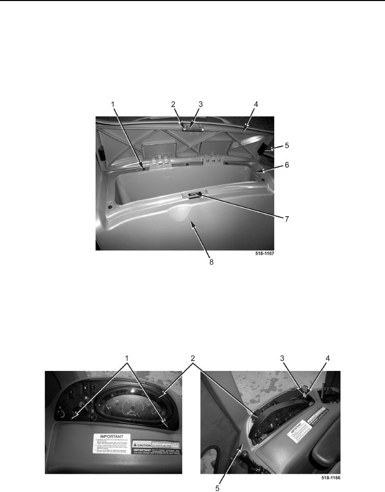
INSTRUMENT PANEL RIGHT-SIDE COVER (REAR) INSTALLATION CONTINUED
4. Install magnetic catch (Figure 18, Item 7) on storage box (Figure 18, Item 6).
5. Install storage box (Figure 18, Item 6) and five bolts (Figure 18, Item 1) on right-side cover (rear)
(Figure 18, Item 8).
6. Install two bumpers (Figure 18, Item 5) on storage box lid (Figure 18, Item 4).
7. Install two catch plates (Figure 18, Item 3) and screws (Figure 18, Item 2) on storage box lid
(Figure 18, Item 4).
Figure 18. Storage Box.
0176
8. Install right-side cover (rear) (Figure 19, Item 5) in machine.
9. Connect two wiring connectors (Figure 19, Item 3) to accessory outlets (Figure 19, Item 4).
10. Position front instrument bezel (Figure 19, Item 2) on right-side cover (rear) (Figure 19, Item 5).
11. Install two screws (Figure 19, Item 1) on front instrument bezel (Figure 19, Item 2).
Figure 19. Front Instrument Bezel.
0176