
TM 5-2420-231-23-2
0176
INSTRUMENT PANEL RIGHT-SIDE COVER (FRONT) INSTALLATION CONTINUED
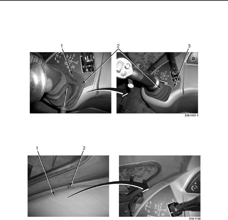
2. Install right-side cover (front) (Figure 28, Item 3) on machine.
3. Position loader control boot (Figure 28, Item 2) on right-side cover (front) (Figure 28, Item 3).
4. Install screw (Figure 28, Item 1) on loader control boot (Figure 28, Item 2).
Figure 28. Loader Control Boot.
0176
5. Install bolt (Figure 29, Item 2) on right-side cover (front) (Figure 29, Item 1).
Figure 29. Front Console Upper Bolt.
0176