TM 5-2420-231-23-2
0183
REMOVAL CONTINUED
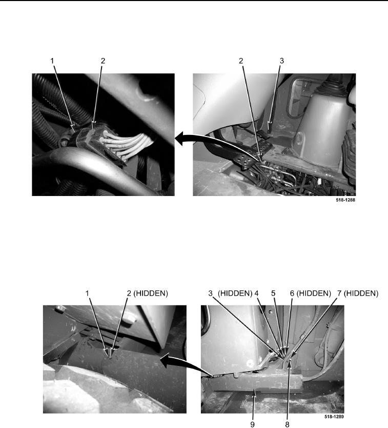
16. Disconnect wiring harness connector (Figure 6, Item 2) from machine wiring harness connector
(Figure 6, Item 1).
Figure 6. Wiring Harness Connector.
0183
17. Remove nut (Figure 7, Item 8), lockwasher (Figure 7, Item 7), spacer (Figure 7, Item 6), bracket (Figure 7,
Item 5), washer (Figure 7, Item 4), and bolt (Figure 7, Item 3) from shield (Figure 7, Item 9). Discard lock-
washer.
18. Remove bolt (Figure 7, Item 1), washer (Figure 7, Item 2) and shield (Figure 7, Item 9) from machine.
Figure 7. Shield.
0183
19. Route wiring harness connector (Figure 6, Item 2) through access hole (Figure 6, Item 3), and remove wiring
harness from machine.
END OF TASK

