
TM 5-2420-231-23-2
0183
INSTALLATION CONTINUED
NOTE
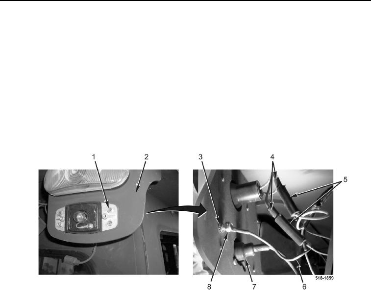
The procedure for marker light and hazard/turn light removal and replacement is identical
for left-hand and right-hand sides. Left-hand marker light and hazard/turn light are shown
in this procedure.
12. Connect two hazard/turn light wiring harness connectors (Figure 12, Item 4) to wiring harness connector
(Figure 12, Item 5).
13. Connect marker light wiring harness connector (Figure 12, Item 7) to wiring harness connector
(Figure 12, Item 5).
14. Install wire (Figure 12, Item 6), new lockwasher (Figure 12, Item 3), and new locknut (Figure 12, Item 8) on
bracket (Figure 12, Item 2) and bolt (Figure 12, Item 1).
Figure 12. Marker Light Ground Wire.
0183