
TM 5-2420-231-23-2
0194
REMOVAL CONTINUED
8. Remove wire lock (Figure 5, Item 2) from A-post blackout wiring harness connector (Figure 5, Item 1).
Figure 5. Wire Lock.
0194
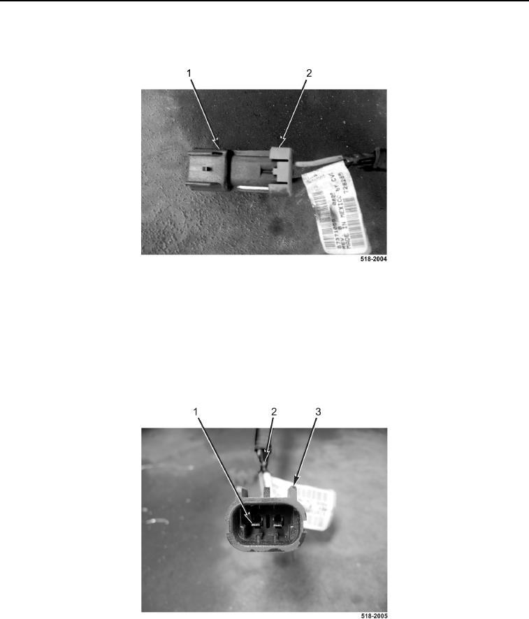
9. Using miniature pick, remove pins (Figure 6, Item 1) from A-post blackout wiring harness connector
(Figure 6, Item 3).
10. Attach mechanic's wire to A-post blackout wiring harness (Figure 6, Item 2).
11. With assistance, remove A-post blackout wiring harness (Figure 6, Item 2) from machine.
12. Remove mechanic's wire from A-post blackout wiring harness (Figure 6, Item 2).
Figure 6. A-Post Blackout Wiring Harness.
0194
END OF TASK