
8
TM 5-2420-231-23-2
FIELD MAINTENANCE
-
A-POST BLACKOUT LAMP WIRING HARNESS REPLACEMENT
0194
Removal, Cleaning and Inspection, Installation
INITIAL SETUP
Tools and Special Tools
References
Tool Kit, General Mechanic's
WP 0369
0
0
(WP 0376, Item 117)
WP 0370
0
Tool Kit, Electrical Contact (WP 0376, Item 116)
WP 0374 (Group Number 0318 and 0706)
0
0
Tool, Pick O-ring (WP 0376, Item 111)
0
Equipment Conditions
Materials/Parts
Machine parked (TM 5-2420-231-10)
0
Rag, Wiping (WP 0375, Item 25)
Batteries disconnected (WP 0157)
0
0
Tiedown Strap (WP 0375, Item 35)
0
Estimated Time to Complete
Lockwasher (2)
0
0.7 hr
Mechanic's Wire
0
0
Personnel Required
Two
0
REMOVAL
0194
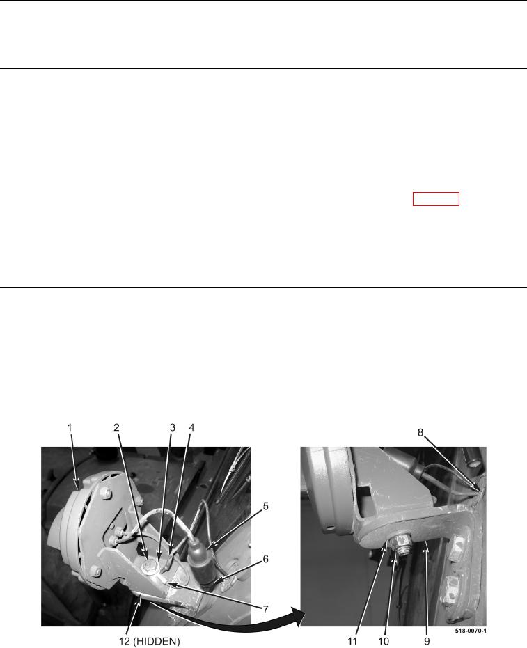
1. Disconnect harness connector (Figure 1, Item 6) from blackout lamp wiring harness connector
(Figure 1, Item 5).
2. Remove nut (Figure 1, Item 10), lockwasher (Figure 1, Item 11), bolt (Figure 1, Item 2), washer (Figure 1,
Item 3), eyelet (Figure 1, Item 4), eyelet (Figure 1, Item 7), front blackout lamp (Figure 1, Item 1), and spacer
(Figure 1, Item 12) from front blackout lamp mount (Figure 1, Item 9). Discard lockwasher.
3. Remove grommet (Figure 1, Item 8) from machine.
Figure 1. Front Blackout Lamp.
0194