
TM 5-2420-231-23-2
0194
CLEANING AND INSPECTION
0194
1. Clean and inspect all parts IAW Mechanical General Maintenance Instructions (WP 0369)
2. Clean and inspect all parts IAW Electrical General Maintenance Instructions (WP 0370).
END OF TASK
INSTALLATION
0194
NOTE
Install wires as noted in removal.
1. Attach mechanic's wire to A-post blackout wiring harness (Figure 6, Item 2).
2. With assistance, route A-post blackout lamp wiring harness (Figure 6, Item 2) on machine.
3. Remove mechanic's wire from wires (Figure 6, Item 2).
4. Install pins (Figure 6, Item 1) in A-post blackout wiring harness connector (Figure 6, Item 3).
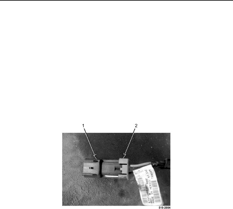
5. Install wire lock (Figure 7, Item 2) on A-post blackout wiring harness connector (Figure 7, Item 1).
Figure 7. Wire Lock.
0194