TM 5-2420-231-23-2
0201
INSTALLATION CONTINUED
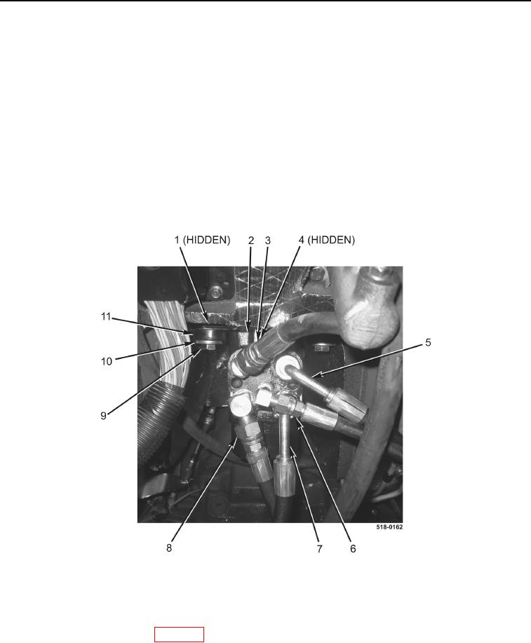
7. Install three isolators (Figure 4, Item 1), new seal (Figure 4, Item 4), steering control valve (Figure 4, Item 2),
three isolators (Figure 4, Item 11), washers (Figure 4, Item 10), and bolts (Figure 4, Item 9) on machine.
NOTE
Remove plugs and caps from hoses and fittings.
Install lines as tagged and marked during removal.
8. Connect left turn hose (Figure 4, Item 5) to steering control valve (Figure 4, Item 2).
9. Connect right turn hose (Figure 4, Item 7) to steering control valve (Figure 4, Item 2).
10. Connect return hose (Figure 4, Item 3) to steering control valve (Figure 4, Item 2).
11. Connect lower hydraulic pump hose (Figure 4, Item 8) to steering control valve (Figure 4, Item 2).
12. Connect upper hydraulic pump hose (Figure 4, Item 6) to steering control valve (Figure 4, Item 2).
Figure 4. Steering Control Valve and Hoses.
0201
END OF TASK
FOLLOW-ON TASKS
0201
Install air cleaner barrier curtain (WP 0099).
END OF TASK
END OF WORK PACKAGE
0201-5/(6 blank)

