
TM 5-2420-231-23-2
0201
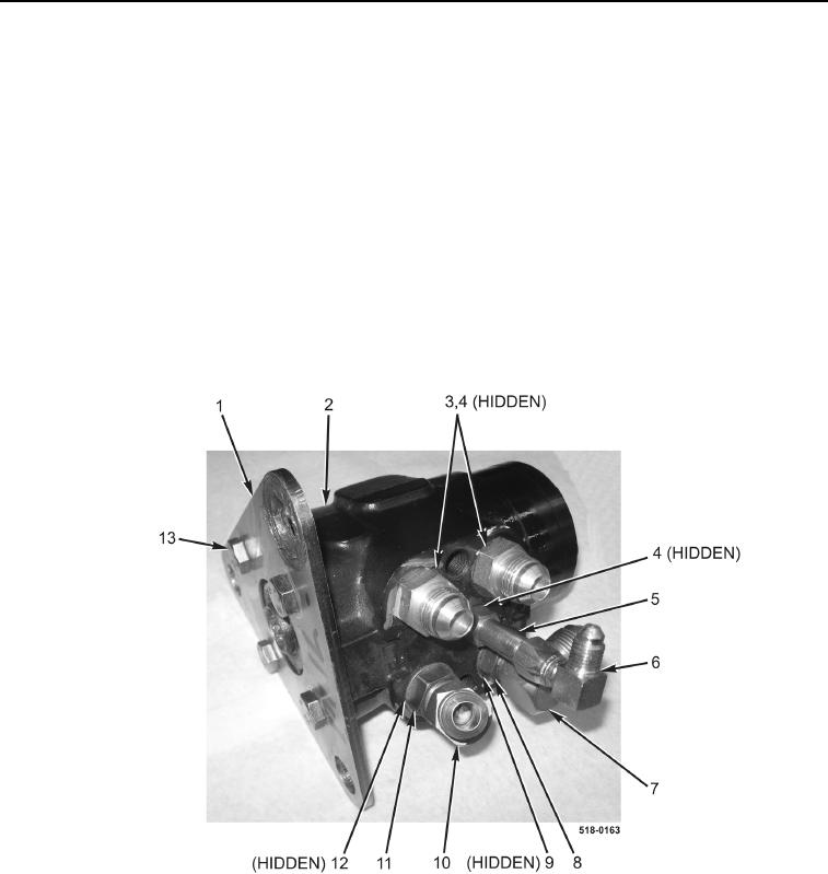
REMOVAL CONTINUED
NOTE
Note position and orientation of fittings to aid in installation.
7. Remove two fittings (Figure 2, Item 3) and O-rings (Figure 2, Item 4) from steering control valve (Figure 2,
Item 2). Discard O-rings.
8. Remove fitting (Figure 2, Item 6) from fitting (Figure 2, Item 5).
9. Remove fitting (Figure 2, Item 5) and O-ring (Figure 2, Item 4) from steering control valve (Figure 2, Item 2).
Discard O-ring.
10. Loosen nut (Figure 2, Item 11) and remove fitting (Figure 2, Item 10) and O-ring (Figure 2, Item 12) from steer-
ing control valve (Figure 2, Item 2). Discard O-ring.
11. Loosen nut (Figure 2, Item 8) and remove fitting (Figure 2, Item 7) and O-ring (Figure 2, Item 9) from steering
control valve (Figure 2, Item 2). Discard O-ring.
12. Remove four bolts (Figure 2, Item 13) and mounting plate (Figure 2, Item 1) from steering control valve
(Figure 2, Item 2).
Figure 2. Steering Control Valve Fittings.
0201
END OF TASK
CLEANING AND INSPECTION
0201
Clean and inspect all parts IAW Mechanical General Maintenance Instructions (WP 0369).
END OF TASK