
TM 5-2420-231-23-2
0201
INSTALLATION
0201
NOTE
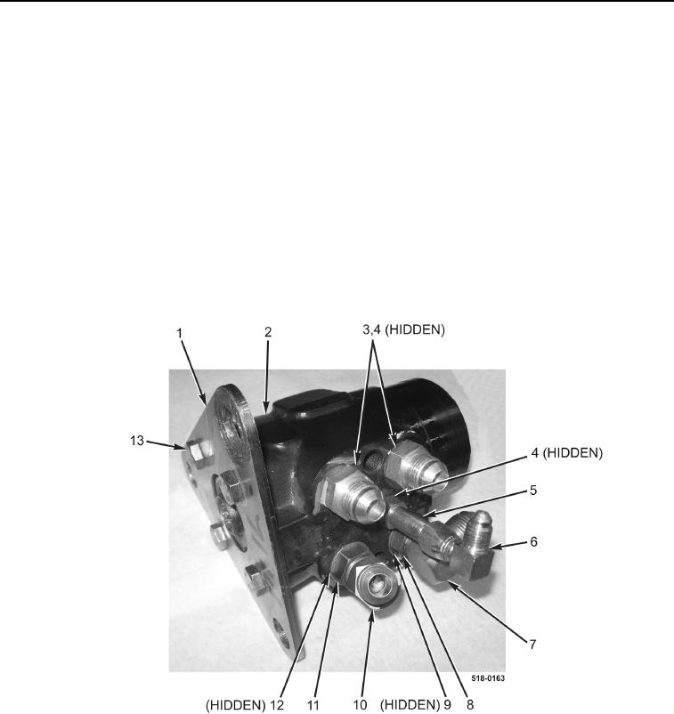
Install fittings in position and orientation noted during removal.
1. Install mounting plate (Figure 3, Item 1) and four bolts (Figure 3, Item 13) on steering control valve
(Figure 3, Item 2).
2. Install new O-ring (Figure 3, Item 9) and fitting (Figure 3, Item 7) on steering control valve (Figure 3, Item 2)
and tighten nut (Figure 3, Item 8).
3. Install new O-ring (Figure 3, Item 12) and fitting (Figure 3, Item 10) on steering control valve (Figure 3, Item 2)
and tighten nut (Figure 3, Item 11).
4. Install new O-ring (Figure 3, Item 4) and fitting (Figure 3, Item 5) on steering control valve (Figure 3, Item 2).
5. Install fitting (Figure 3, Item 6) on fitting (Figure 3, Item 5).
6. Install two new O-rings (Figure 3, Item 4) and fittings (Figure 3, Item 3) on steering control valve
(Figure 3, Item 2).
Figure 3. Steering Control Valve Fittings.
0201