
TM 5-2420-231-23-2
0202
REMOVAL CONTINUED
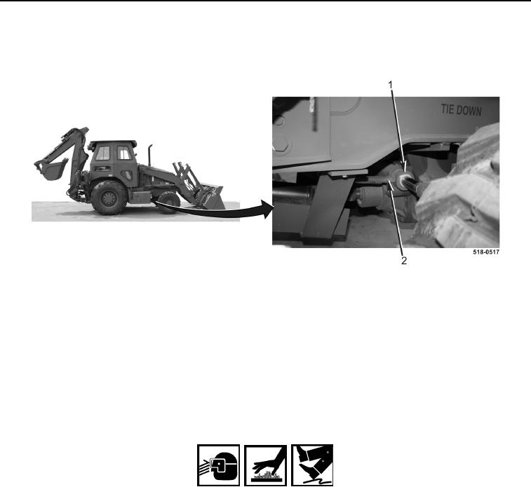
13. Disconnect right turn hose (Figure 8, Item 2) from steering cylinder (Figure 8, Item 1) and remove hose from
machine.
Figure 8. Right Turn Hose.
0202
END OF TASK
CLEANING AND INSPECTION
0202
Clean and inspect all parts IAW Mechanical General Maintenance Instructions (WP 0369).
END OF TASK
INSTALLATION
0202
WARNING
Allow hydraulic system to cool before performing procedure. Hot hydraulic fluid can cause
severe burns. Wear eye, hand, and skin protection when working with heated parts.
Hydraulic oil is very slippery. Immediately wipe up any spills.
Failure to follow these warnings may result in injury or death to personnel.
NOTE
Install lines as tagged and marked during removal.
Remove plugs and caps from hoses and fittings.
Route hoses as noted during removal.
1. Connect right turn hose (Figure 8, Item 2) to steering cylinder (Figure 8, Item 1) and route hose on machine.