
TM 5-2420-231-23-2
0202
INSTALLATION CONTINUED
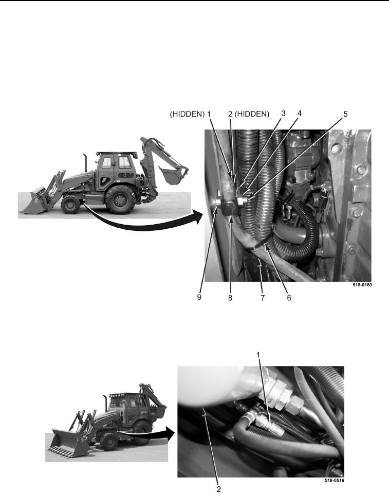
4. Install bolt (Figure 11, Item 5), spacer (Figure 11, Item 9), clamp (Figure 11, Item 3), new lockwasher
(Figure 11, Item 1), nut (Figure 11, Item 2), clamp (Figure 11, Item 8), and nut (Figure 11, Item 4) on frame rail.
NOTE
Install tiedown straps in quantity and location noted during removal.
5. Install new tiedown straps (Figure 11, Item 6) on hydraulic hoses (Figure 11, Item 7).
Figure 11. Left Frame Rail.
0202
6. Connect return hose (Figure 12, Item 1) to hydraulic oil filter (Figure 12, Item 2) and route hose on machine.
Figure 12. Return Hose.
0202