
TM 5-2420-231-23-2
0202
INSTALLATION CONTINUED
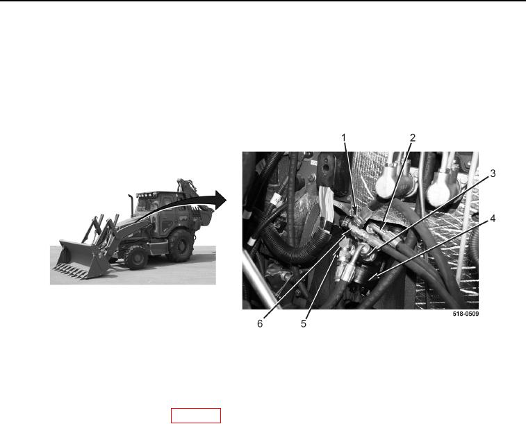
9. Connect left turn hose (Figure 15, Item 2) to steering control valve (Figure 15, Item 4).
10. Connect right turn hose (Figure 15, Item 3) to steering control valve (Figure 15, Item 4).
11. Connect return hose (Figure 15, Item 1) to steering control valve (Figure 15, Item 4).
12. Connect lower hydraulic pump hose (Figure 15, Item 5) to steering control valve (Figure 15, Item 4).
13. Connect upper hydraulic pump hose (Figure 15, Item 6) to steering control valve (Figure 15, Item 4).
Figure 15. Steering Control Valve.
0202
END OF TASK
FOLLOW-ON TASKS
0202
1. Install air cleaner barrier curtain (WP 0099).
2. Install floor cover plates (WP 0306).
END OF TASK
END OF WORK PACKAGE