
TM 5-2420-231-23-2
0208
REMOVAL CONTINUED
NOTE
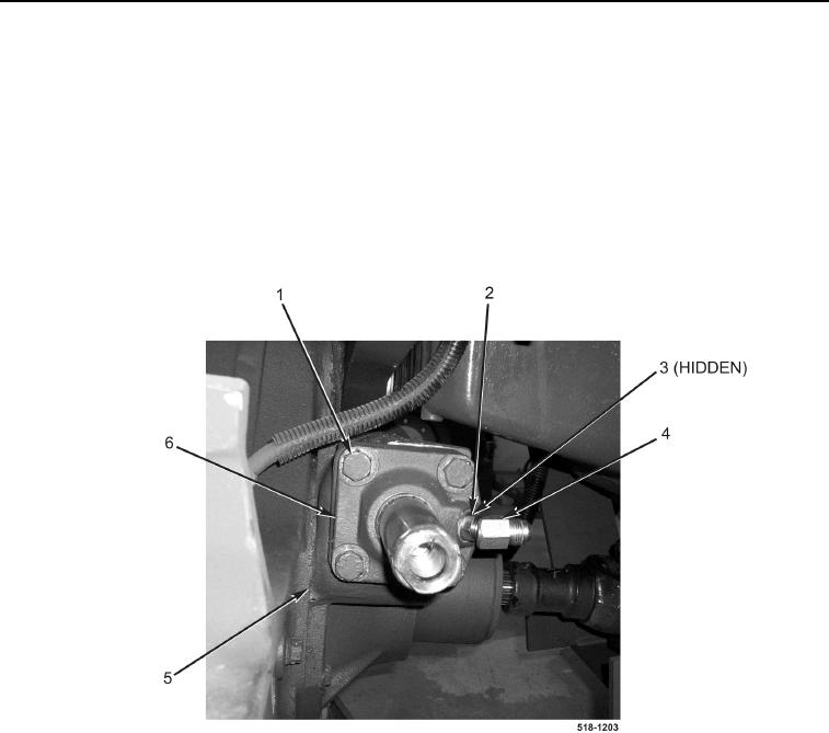
Note position of fitting to aid in installation.
Note orientation of cylinder to aid in installation.
3. Loosen nut (Figure 3, Item 2), remove left fitting (Figure 3, Item 4) and O-ring (Figure 3, Item 3) from cylinder
(Figure 3, Item 6). Discard O-ring.
4. Remove four bolts (Figure 3, Item 1) from cylinder (Figure 3, Item 6).
5. Use dead blow hammer to drive cylinder (Figure 3, Item 6) out of housing (Figure 3, Item 5).
Figure 3. Cylinder Bolts.
0208
END OF TASK
CLEANING AND INSPECTION
0208
Clean and inspect all parts IAW Mechanical General Maintenance Instructions (WP 0369).
END OF TASK