
TM 5-2420-231-23-2
0209
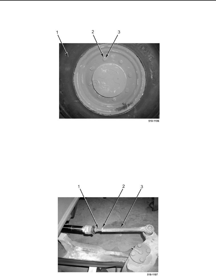
REMOVAL CONTINUED
2. Remove 16 nuts (Figure 2, Item 3), washers (Figure 2, Item 2), and two front wheel and tire assemblies
(Figure 2, Item 1) from machine.
Figure 2. Front Wheel and Tire Assemblies.
0209
NOTE
The procedure for tie rod removal and replacement is identical for left-hand and right-hand
side. Left-hand tie rod is shown in this procedure.
Note position of tie rod end on inner tie rod threaded shaft to aid in installation.
3. Loosen jamnut (Figure 3, Item 2) from tie rod end (Figure 3, Item 3) on inner tie rod threaded shaft
(Figure 3, Item 1).
Figure 3. Tie Rod Jamnut.
0209