
TM 5-2420-231-23-2
0208
INSTALLATION
0208
WARNING
Allow hydraulic system to cool before performing procedure. Hot hydraulic fluid can cause
severe burns. Wear eye, hand, and skin protection when working with heated parts.
Hydraulic oil is very slippery. Immediately wipe up any spills.
Failure to follow these warnings may result in injury or death to personnel.
NOTE
Install fitting as noted during removal.
Install cylinder in orientation noted during removal.
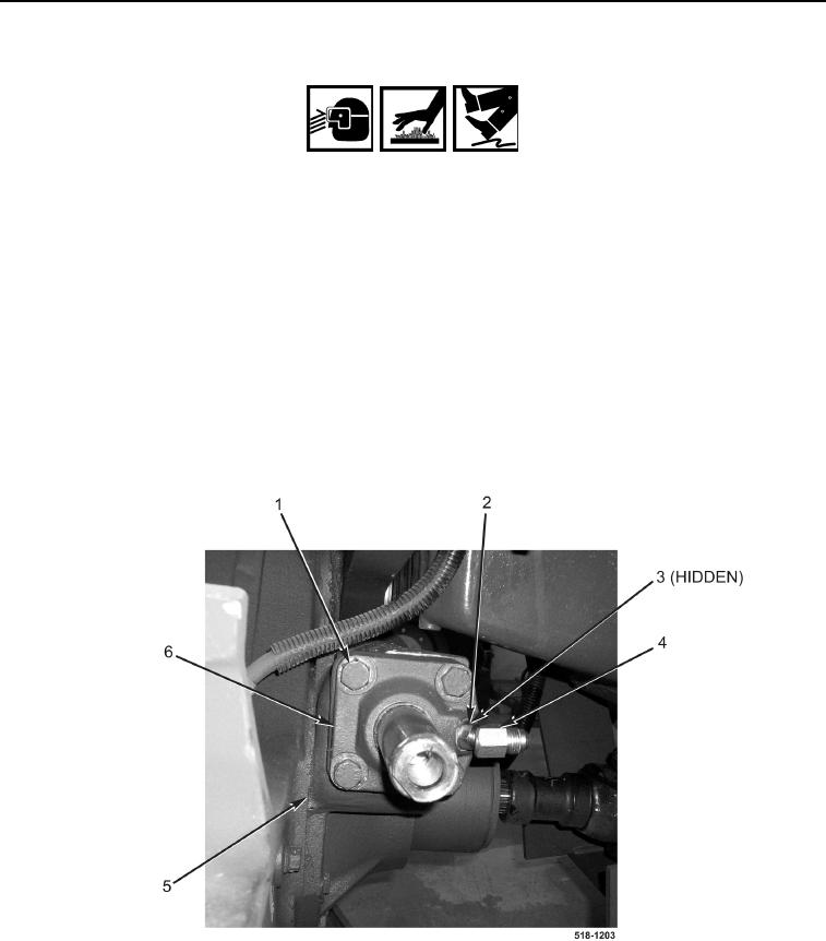
1. Use dead blow hammer to drive steering cylinder (Figure 4, Item 6) in axle housing (Figure 4, Item 5).
2. Install four bolts (Figure 4, Item 1) on steering cylinder (Figure 4, Item 6). Torque to 89 lb-ft (120 Nm).
3. Install new O-ring (Figure 4, Item 3) and left fitting (Figure 4, Item 4) on steering cylinder (Figure 4, Item 6) and
tighten nut (Figure 4, Item 2).
Figure 4. Steering Cylinder.
0208