
TM 5-2420-231-23-2
0211
INSTALLATION CONTINUED
NOTE
Install tiedown straps in location and quantity noted during removal.
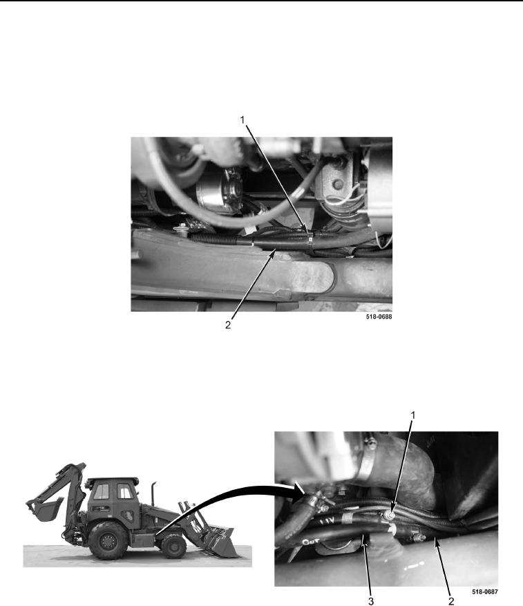
7. Install new tiedown straps (Figure 14, Item 1) on oil cooler hoses (Figure 14, Item 2).
Figure 14. Tiedown Straps.
0211
8. Connect two transmission oil cooler hoses (Figure 15, Item 3) and install clamps (Figure 15 Item 1) on trans-
mission/hydraulic oil cooler (Figure 15, Item 2).
Figure 15. Right-Side Transmission Oil Cooler Hoses.
0211