
TM 5-2420-231-23-2
0214
REMOVAL CONTINUED
WARNING
Be mindful of the position of your hands while removing the mounting brackets. The
engine and transmission assembly is totally supported by the lifting equipment at this
point. Never allow your fingers or any other part of your body to be in a pinch-point. Failure
to follow this warning may result in death or injury to personnel.
NOTE
The transmission can be moved right to left slightly while supported by the lifting
equipment for better access to the rear mount bolts. Remove the left-side mount bracket
first to ensure there is enough space.
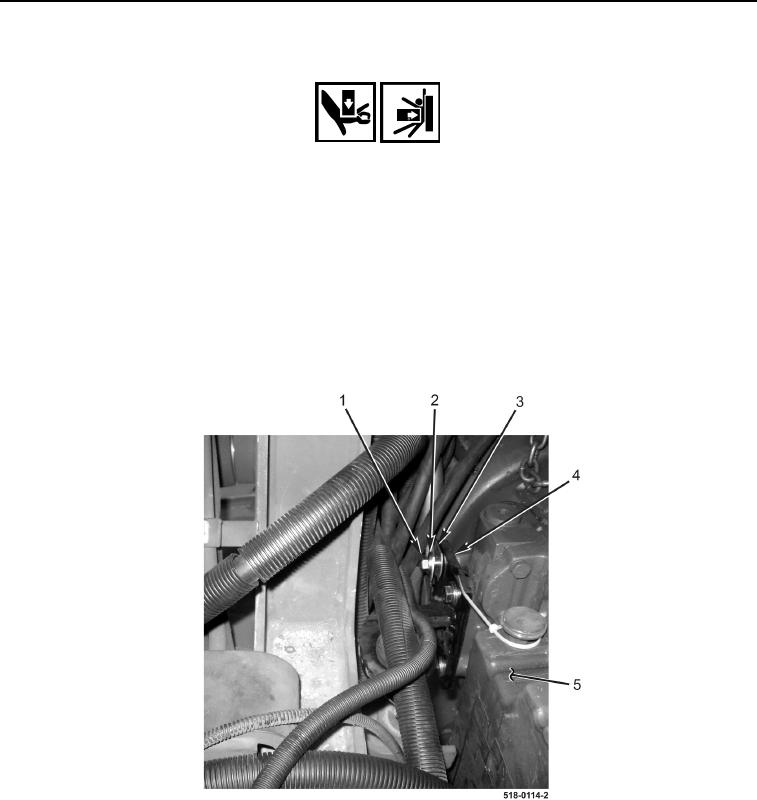
6. Remove four bolts (Figure 4, Item 1), washers (Figure 4, Item 2), transmission dipstick tube clamp (Figure 4,
Item 3), and left transmission mount bracket (Figure 4, Item 4) from transmission (Figure 4, Item 5).
Figure 4. Left Transmission Mount Bracket.
0214