
TM 5-2420-231-23-2
0213
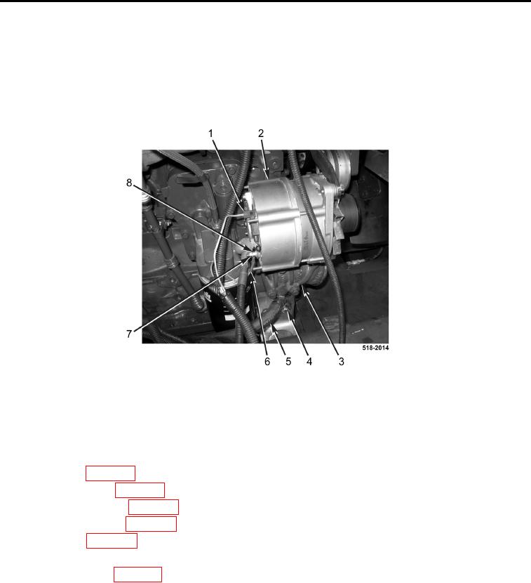
INSTALLATION CONTINUED
75. Connect wire (Figure 55, Item 6) and install new lockwasher (Figure 55, Item 8) and nut (Figure 55, Item 7) on
alternator (Figure 55, Item 2).
76. Connect wiring harness connector (Figure 55, Item 1) to alternator (Figure 55, Item 2).
77. Connect coolant hose (Figure 55, Item 5), and tighten clamp (Figure 55, Item 4) on water inlet housing
(Figure 55, Item 3).
Figure 55. Alternator.
0213
END OF TASK
FOLLOW-ON TASKS
0213
1. Install cab assembly (WP 0327).
2. Install starter (WP 0152).
3. Install coolant pack (WP 0092).
4. Install front drive shaft (WP 0210).
5. Install rear drive shaft (WP 0222).
6. Fill engine oil (WP 0126).
7. Fill hydraulic system (WP 0301).
8. Fill transmission oil (WP 0216)
9.
END OF TASK
END OF WORK PACKAGE