
TM 5-2420-231-23-2
0218
REMOVAL CONTINUED
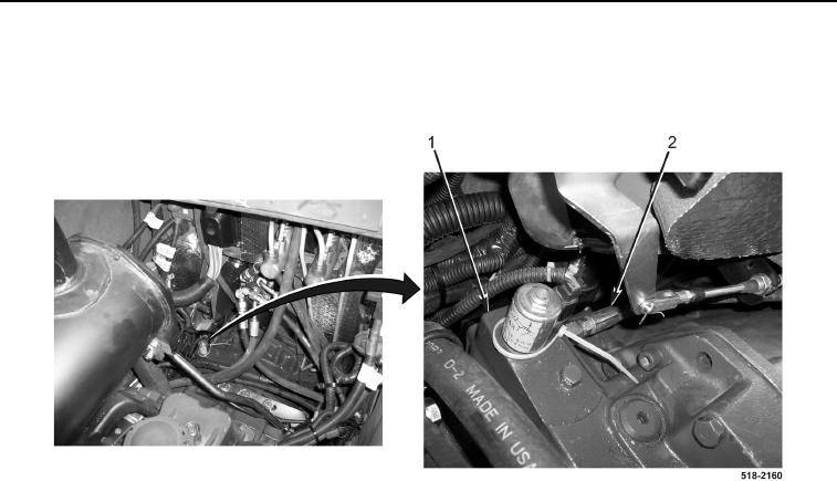
3. Disconnect differential lock hose (Figure 3, Item 2) from transmission (Figure 3, Item 1).
4. Remove differential lock hose (Figure 3, Item 2) from machine.
Figure 3. Differential Lock Hose at Transmission.
0218
END OF TASK
CLEANING AND INSPECTION
0218
Clean and inspect all parts IAW Mechanical General Maintenance Instructions (WP 0369).
END OF TASK
INSTALLATION
0218
NOTE
Install lines as tagged and marked during removal.
Remove plugs and caps from hoses and fittings.
1. Position differential lock hose (Figure 3, Item 2) on machine.
2. Connect differential lock hose (Figure 3, Item 2) to transmission (Figure 3, Item 1).