TM 5-2420-231-23-2
0217
ASSEMBLY CONTINUED
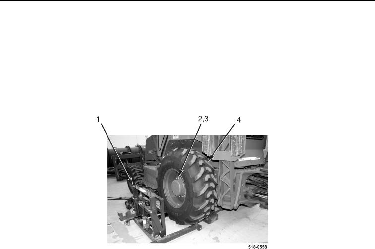
5. Using suitable lifting device, install wheel and tire assembly (Figure 4, Item 4) on machine.
6. Install 10 washers (Figure 4, Item 3) and nuts (Figure 4, Item 2) on wheel and tire assembly (Figure 4,
Item 4).Tighten in three steps:
a. Torque to 100 lb-ft (136 Nm).
b. Torque to 200 lb-ft (271 Nm).
c.
Torque to 225 lb-ft (305 Nm).
7. Position suitable lifting device (Figure 4, Item 1) aside.
Figure 4. Wheel and Tire Assembly.
0217
8. Inspect all rim components to ensure that they are properly seated.
WARNING
Inflate the tire only when the wheel is bolted on the machine with lug nuts fully tightened.
Never inflate tire over 40 psi (276 kPa) to seat tire bead. Use a pneumatic tire inflator-
gauge and a 10 ft (3.1 m) air hose to inflate tire. If beads do not seat, disassemble tire and
inspect all components before reassembly.
Failure to follow this warning may result in injury or death to personnel.
9. Inflate tire to 40 psi (276 kPa) to seat both tire beads. Both tire beads should seat before reaching 40 psi
(276 kPa). If tire beads fail to seat, deflate tire, determine cause of failure, take corrective action, add additional
tire and rim lubricant, and repeat this step.
10. Visually check to see that all rim components are properly seated and allow tire to deflate.
11. Install valve core in valve stem.
12. Inflate tire to normal operating pressure TP 38 psi. Visually inspect all rim components to ensure that they are
properly seated.
13. Check bead, valve stem, and valve core for leaks.
14. Install valve cap onto valve stem finger-tight.
END OF TASK

