
16
TM 5-2420-231-23-3
FIELD MAINTENANCE
-
LOADER LIFT CYLINDER HYDRAULIC TUBES REPLACEMENT
0233
Right-Hand Tubes Removal, Left-Hand Tubes Removal, Cleaning and Inspection,
Left-Hand Tubes Installation, Right-Hand Tubes Installation
INITIAL SETUP
References
Tools and Special Tools
Tool Kit, General Mechanic's
TM 5-2420-231-10
0
0
(WP 0376, Item 117)
0
Pan, Drain, 5 gal. Capacity (WP 0376, Item 54)
WP 0374 (Group Number 0704 and 0706)
0
0
Materials/Parts
Equipment Conditions
Rag, Wiping (WP 0375, Item 25)
Front floor cover plate removed (WP 0306)
0
0
Tiedown Strap (WP 0375, Item 35)
0
Estimated Time to Complete
Lockwasher (6)
0
1.4 hr
0
Personnel Required
Two
0
RIGHT-HAND TUBES REMOVAL
0233
1. Remove cap from hydraulic tank (TM 5-2420-231-10).
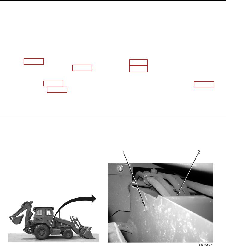
2. Remove bolt (Figure 1, Item 1) from right hose cover (Figure 1, Item 2).
Figure 1. Right Hose Cover.
0233