
TM 5-2420-231-23-3
0233
RIGHT-HAND TUBES REMOVAL CONTINUED
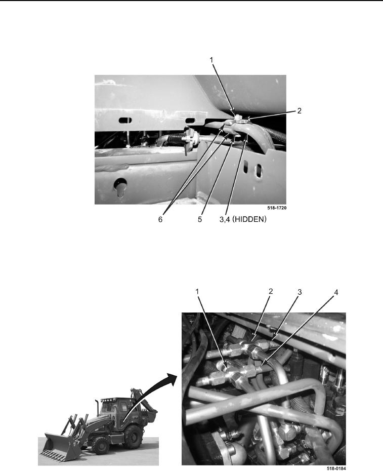
7. Remove bolt (Figure 5, Item 5), nut (Figure 5, Item 1), lockwasher (Figure 5, Item 2), two brackets
(Figure 5, Item 6), and spacer (Figure 5, Item 4) from two tubes (Figure 5, Item 3). Discard lockwasher.
Figure 5. Rear Bracket (Right-Hand).
0233
8. Disconnect tube (Figure 6, Item 4) from fitting (Figure 6, Item 1).
9. Disconnect tube (Figure 6, Item 3) from fitting (Figure 6, Item 2).
10. With assistance, remove two tubes (Figure 6, Items 4 and 3) from machine.
Figure 6. Tubes (Right-Hand).
0233
END OF TASK