
TM 5-2420-231-23-3
0235
INSTALLATION CONTINUED
NOTE
The procedure for loader cylinder removal and replacement is identical for left-hand and
right-hand loader cylinder. Left-hand loader bucket cylinder is shown in this procedure.
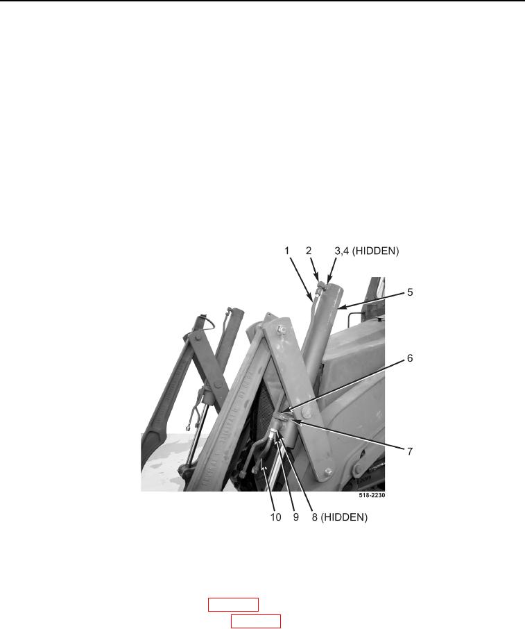
21. Install new O-ring (Figure 12, Item 8) and fitting (Figure 12, Item 9) on loader bucket cylinder
(Figure 12, Item 5).
22. Install new O-ring (Figure 12, Item 4) and fitting (Figure 12, Item 2) on loader bucket cylinder (Figure 12,
Item 5) and tighten nut (Figure 12, Item 3).
23. Connect tube (Figure 12, Item 10) to fitting (Figure 12, Item 9).
24. Connect tube (Figure 12, Item 1) to fitting (Figure 12, Item 2).
25. Install resilient mount (Figure 12, Item 6) and clamp (Figure 12, Item 7) on loader bucket cylinder
(Figure 12, Item 5).
26. Repeat steps 21 through 25 for right-hand loader bucket cylinder tubes.
Figure 12. Left Loader Bucket Cylinder.
0235
END OF TASK
FOLLOW-ON TASKS
0235
1. Install loader lift cylinder hydraulic tubes (WP 0233).
2. Install loader bucket cylinder hydraulic hoses (WP 0232).
END OF TASK
END OF WORK PACKAGE