
TM 5-2420-231-23-3
0236
CLEANING AND INSPECTION
0236
Clean and inspect all parts IAW Mechanical General Maintenance Instructions (WP 0369).
END OF TASK
INSTALLATION
0236
NOTE
Install lines as tagged and marked during removal.
Route lines as noted during removal.
Remove plugs and caps from hoses and fittings.
1. With assistance, position two tubes (Figure 8, Item 1) on machine.
2. Connect two tubes (Figure 8, Item 1) on loader valve (Figure 8, Item 2).
NOTE
Install tiedown straps in location and quantity noted during removal.
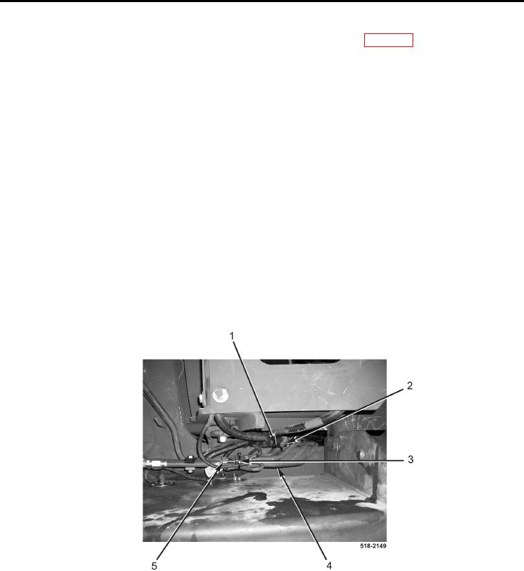
3. Install new tiedown straps (Figure 9, Item 1) on tube (Figure 9, Item 2).
4. Install new tiedown straps (Figure 9, Item 3) on tube (Figure 9, Item 4) and connector (Figure 9, Item 5).
Figure 9. Tiedowns.
0236