
TM 5-2420-231-23-3
0236
INSTALLATION CONTINUED
NOTE
Install lines as tagged and marked during removal.
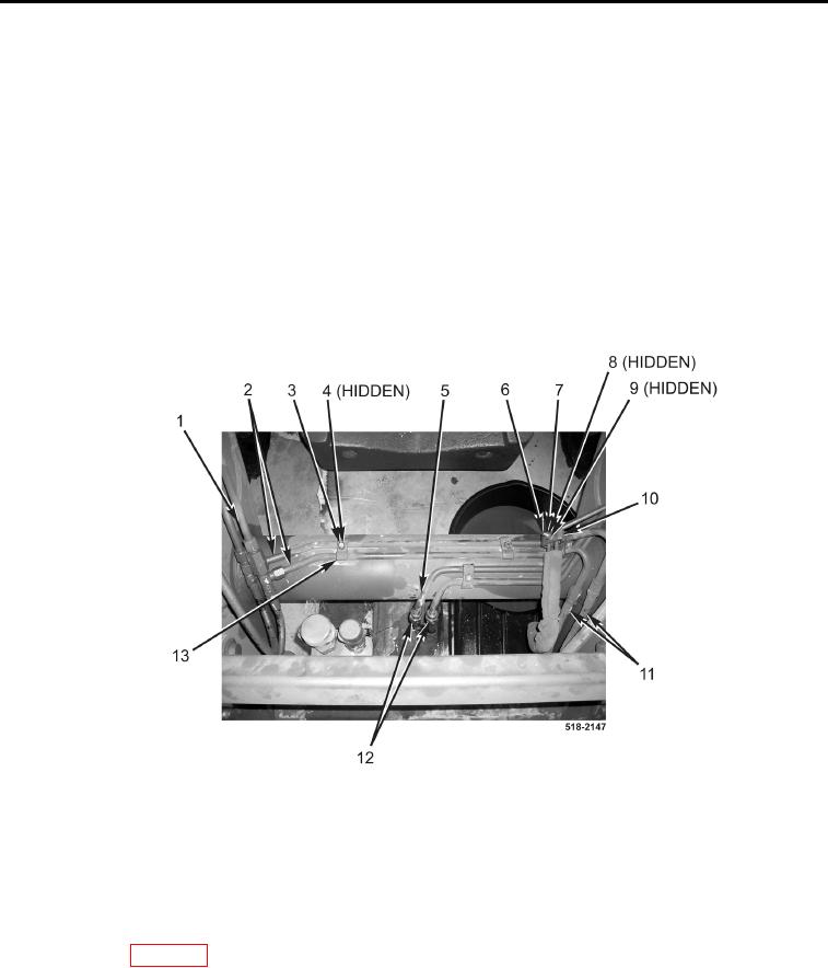
16. Connect two tubes (Figure 15, Item 5) to hoses (Figure 15, Item 12).
17. Install two tubes (Figure 15, Item 2) on machine.
18. Connect two tubes (Figure 15, Item 2) to hoses (Figure 15, Item 11).
19. Connect two tubes (Figure 15, Item 2) to fittings (Figure 15, Item 1).
20. Install spacer (Figure 15, Item 9), four clamps (Figure 15, Item 10), bolt (Figure 15, Item 6), new lockwasher
(Figure 15, Item 8), and nut (Figure 15, Item 7) on tubes (Figure 15, Item 2).
21. Install three clamps (Figure 15, Item 13), new lockwashers (Figure 15, Item 4), and nuts (Figure 15, Item 3) on
tubes (Figure 15, Item 2) and tubes (Figure 15, Item 5).
Figure 15. Front Connections.
0236
22. Install cap on hydraulic tank (TM 5-2420-231-10).
END OF TASK
FOLLOW-ON TASKS
0236
Install floor plate (WP 0306).
END OF TASK
END OF WORK PACKAGE