
TM 5-2420-231-23-3
0236
INSTALLATION CONTINUED
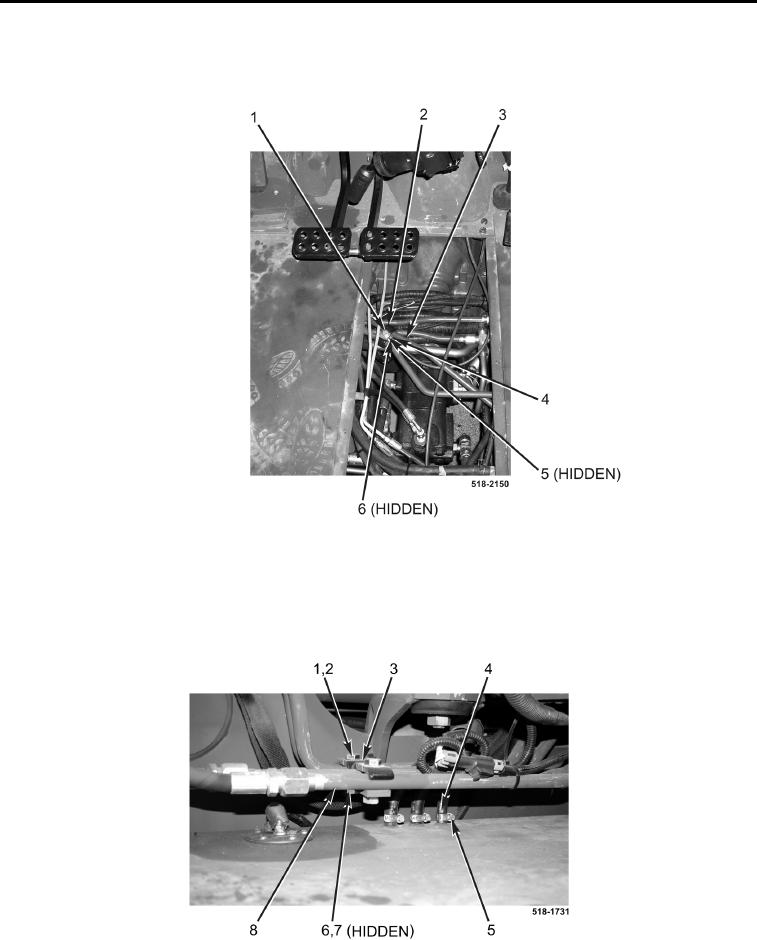
5. Install spacer (Figure 10, Item 4), two brackets (Figure 10, Item 2), bolt (Figure 10, Item 1), new lockwasher
(Figure 10, Item 5), and nut (Figure 10, Item 6) on two tubes (Figure 10, Item 3).
Figure 10. Bracket.
0236
6. Install spacer (Figure 11, Item 7), bracket (Figure 11, Item 3), bolt (Figure 11, Item 1), new lockwasher
(Figure 11, Item 2), and nut (Figure 11, Item 6) on two tubes (Figure 11, Item 8).
7. Connect three hoses (Figure 11, Item 4) to fuel tank and tighten three clamps (Figure 11, Item 5).
Figure 11. Fuel Hoses and Bracket.
0236