
TM 5-2420-231-23-3
0240
INSTALLATION
0240
WARNING
Allow hydraulic system to cool before performing procedure. Hot metal parts can cause
severe burns. Wear eye, hand, and skin protection when working with heated parts.
Hydraulic oil is very slippery. Immediately wipe up any spills. Failure to follow this warning
may result in injury or death to personnel.
NOTE
Remove plugs and caps from hoses and fittings.
Install lines as tagged and marked during removal.
Route lines as noted during removal.
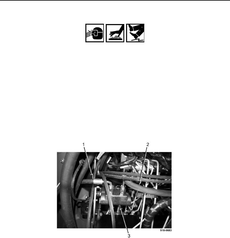
1. Position hydraulic hose (Figure 5, Item 2) on machine.
2. Connect hydraulic hose (Figure 5, Item 2) to valve assembly (Figure 5, Item 3).
3. Position hydraulic hose (Figure 5, Item 1) on machine.
4. Connect hydraulic hose (Figure 5, Item 1) to valve assembly (Figure 5, Item 3).
Figure 5. Valve Assembly.
0240