TM 5-2420-231-23-3
0240
INSTALLATION CONTINUED
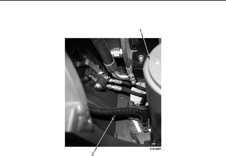
7. Connect hydraulic hose (Figure 7, Item 2) to backhoe swing cylinder (Figure 7, Item 1).
Figure 7. Hydraulic Hose at Right Backhoe Swing Cylinder.
0240
8. Position hydraulic hose (Figure 8, Item 1) on machine.
9. Connect hydraulic hose (Figure 8, Item 1) to backhoe swing cylinder (Figure 8, Item 4).
10. Connect hydraulic hose (Figure 8, Item 1) to backhoe swing cylinder (Figure 8, Item 7).
11. Position hydraulic hose (Figure 8, Item 5) on machine.
12. Connect hydraulic hose (Figure 8, Item 5) to backhoe swing cylinder (Figure 8, Item 4).
13. Connect hydraulic hose (Figure 8, Item 5) to backhoe swing cylinder (Figure 8, Item 7).
14. Install resilient mount (Figure 8, Item 2) and clamp (Figure 8, Item 3) on backhoe swing cylinder
(Figure 8, Item 4).
15. Install resilient mount (Figure 8, Item 8) and clamp (Figure 8, Item 6) on backhoe swing cylinder
(Figure 8, Item 7).

