
TM 5-2420-231-23-3
0244
INSTALLATION CONTINUED
36. Install clamp (Figure 33, Item 1), new lockwasher (Figure 33, Item 2), and bolt (Figure 33, Item 4) on hoses
(Figure 33, Item 3).
37. Install clamp (Figure 33, Item 6), new lockwasher (Figure 33, Item 8), and bolt (Figure 33, Item 7) on hose
(Figure 33, Item 5) and clamp (Figure 33, Item 1).
Figure 33. Left Auxiliary Hose Clamp.
0244
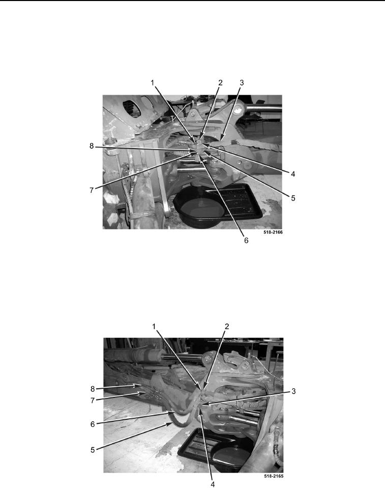
38. Connect hose (Figure 34, Item 6) to tube (Figure 34, Item 8).
39. Connect hose (Figure 34, Item 5) to tube (Figure 34, Item 7).
40. Install insulator (Figure 34, Item 1), clamp (Figure 34, Item 2), washer (Figure 34, Item 4), and bolt (Figure 34,
Item 3) on hoses (Figure 34, Items 5 and 6).
Figure 34. Right Auxiliary Hose Connection.
0244