
TM 5-2420-231-23-3
0244
INSTALLATION CONTINUED
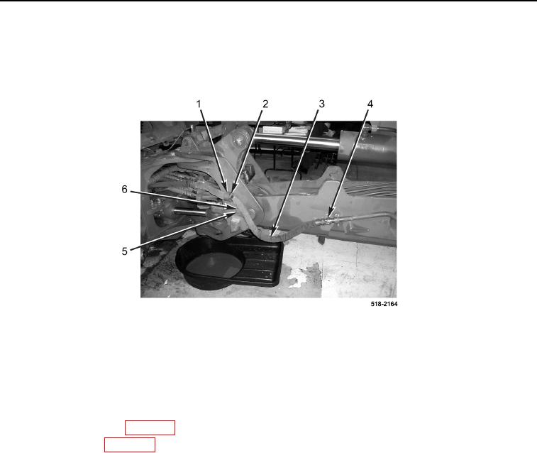
41. Connect hose (Figure 35, Item 3) to tube (Figure 35, Item 4).
42. Install two insulators (Figure 35, Item 2), clamp (Figure 35, Item 1), washer (Figure 35, Item 6), and bolt
(Figure 35, Item 5) on hose (Figure 35, Item 3).
Figure 35. Left Auxiliary Hose Connection.
0244
43. Install cap on hydraulic tank (TM 5-2420-231-10).
END OF TASK
FOLLOW-ON TASKS
0244
1. Install rear floor plate (WP 0306).
2. Install rear cover (WP 0326).
3. Check hydraulic fluid and fill as necessary (TM 5-2420-231-10).
END OF TASK
END OF WORK PACKAGE