
TM 5-2420-231-23-3
0254
REMOVAL CONTINUED
Figure 2. Ride Control Solenoid Valve.
0254
NOTE
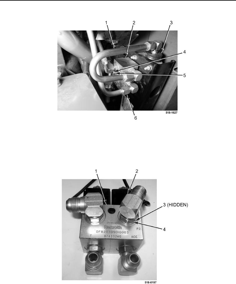
Note position and orientation of hydraulic fittings to aid in installation.
10. Loosen four nuts (Figure 3, Item 4) and remove elbow fittings (Figure 3, Item 2) and O-rings (Figure 3, Item 3)
from ride control solenoid valve (Figure 3, Item 1). Discard O-rings.
Figure 3. Ride Control Solenoid Valve Fittings.
0254
END OF TASK