
TM 5-2420-231-23-3
0254
INSTALLATION CONTINUED
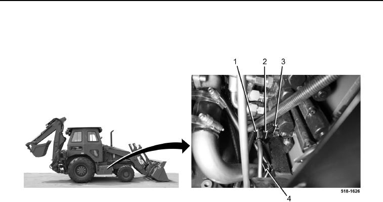
7. Connect two solenoid connectors (Figure 6, Item 2) to wiring harness (Figure 6, Item 3).
8. Install new tiedown strap (Figure 6, Item 1) on tube (Figure 6, Item 4).
Figure 6. Solenoid Connectors.
0254
9. Install cap on hydraulic tank (TM 5-2420-231-10).
END OF TASK
FOLLOW-ON TASKS
0254
Check hydraulic oil level and fill as necessary (TM 5-2420-231-10).
END OF TASK
END OF WORK PACKAGE