
TM 5-2420-231-23-3
0254
CLEANING AND INSPECTION
0254
1. Clean and inspect all parts IAW Mechanical General Maintenance Instructions (WP 0369).
2. Clean and inspect all parts IAW Electrical General Maintenance Instructions (WP 0370).
END OF TASK
INSTALLATION
0254
NOTE
Install hydraulic fittings in position and orientation noted during removal.
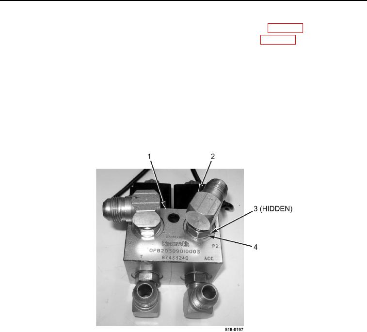
1. Install four new O-rings (Figure 4, Item 3) and fittings (Figure 4, Item 2) on ride control solenoid valve
(Figure 4, Item 1) and tighten nuts (Figure 4, Item 4).
Figure 4. Ride Control Solenoid Valve Fittings.
0254