
TM 5-2420-231-23-3
0269
REMOVAL CONTINUED
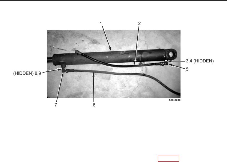
Figure 8. Loader Lift Cylinder Hoses.
0269
20. Repeat steps 6 through 19 for right-hand loader lift cylinder.
END OF TASK
CLEANING AND INSPECTION
0269
Clean and inspect all parts IAW Mechanical General Maintenance Instructions (WP 0369).
END OF TASK
INSTALLATION
0269
NOTE
The procedure for loader cylinder removal and replacement is identical for left-hand and
right-hand loader cylinder. Left-hand loader cylinder is shown in this procedure.
Install fitting in position noted during removal.
1. Install new O-ring (Figure 8, Item 4) and fitting (Figure 8, Item 5) on loader lift cylinder (Figure 8, Item 1) and
tighten nut (Figure 8, Item 3).
2. Connect hose (Figure 8, Item 2) to fitting (Figure 8, Item 5).
3. Install new O-ring (Figure 8, Item 9) and fitting (Figure 8, Item 7) on loader lift cylinder (Figure 8, Item 1) and
tighten nut (Figure 8, Item 8).
4. Connect hose (Figure 8, Item 6) to fitting (Figure 8, Item 7).