
TM 5-2420-231-23-3
0269
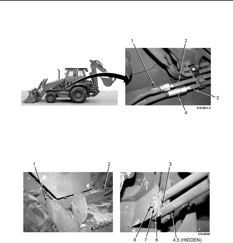
INSTALLATION CONTINUED
12. Connect two hoses (Figure 13, Items 1 and 4) to two tubes (Figure 13, Items 2 and 3).
13. Repeat steps 1 through 12 for right-hand loader lift cylinder.
Figure 13. Hoses.
0269
14. Install cover (Figure 14, Item 2) and bolt (Figure 14, Item 1) on machine.
15. Install spacer (Figure 14, Item 3), two clamps (Figure 14, Item 6), new lockwasher (Figure 14, Item 5), washer
(Figure 14, Item 7), bolt (Figure 14, Item 8), and nut (Figure 14, Item 4) on machine.
Figure 14. Battery Box/Oil Tank Cover.
0269