
TM 5-2420-231-23-3
0269
INSTALLATION CONTINUED
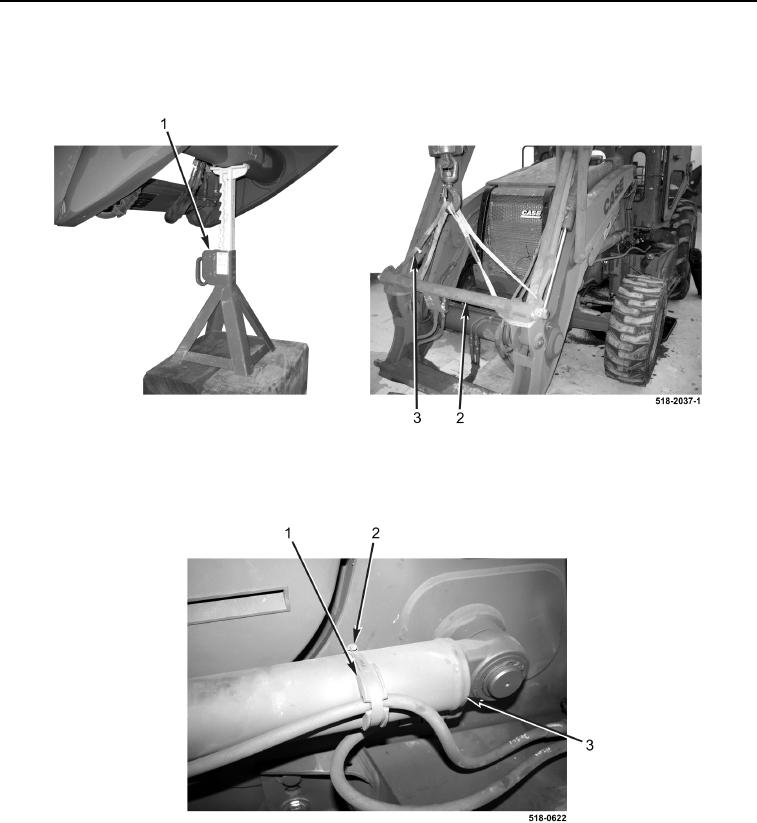
9. Using lifting device, raise loader and remove trestle (Figure 11, Item 1) and cribbing.
10. Lower loader and remove slings (Figure 11, Item 3) and lifting device from coupler (Figure 11, Item 2).
Figure 11. Loader.
0269
11. Install resilient mount (Figure 12, Item 1) and clamp (Figure 12, Item 2) on cylinder (Figure 12, Item 3).
Figure 12. Clamp.
0269