
TM 5-2420-231-23-3
0273
REMOVAL CONTINUED
NOTE
Note orientation of fittings to aid in assembly.
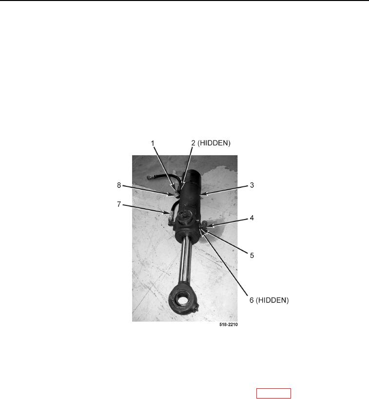
9. Disconnect hydraulic hose (Figure 5, Item 7) from backhoe swing cylinder (Figure 5, Item 3).
10. Loosen nut (Figure 5, Item 1) and remove fitting (Figure 5, Item 8) and O-ring (Figure 5, Item 2) from backhoe
swing cylinder (Figure 5, Item 3). Discard O-ring.
11. Loosen two nuts (Figure 5, Item 5) and remove fittings (Figure 5, Item 4) and O-rings (Figure 5, Item 6) from
backhoe swing cylinder (Figure 5, Item 3). Discard O-rings.
12. Repeat steps 2 through 11 on left-hand backhoe swing cylinder.
Figure 5. Fittings.
0273
END OF TASK
CLEANING AND INSPECTION
0273
Clean and inspect all parts IAW Mechanical General Maintenance Instructions (WP 0369).
END OF TASK